This page talks about the winding patterns generated for the electric machines.
Some terminology here:
Coil span
The number of slot pitches for coil throw on the stator. If the coil goes into the stator on slot 1 and comes out of slot 4, then the coil pitch is 3. This may be expressed in terms of angle(electrical or mechanical), distance(mm) or slot count.
** full pitch coil span = Slots/Poles **.
SPP (slots per pole per phase)
This discloses information about winding factor and the harmonics.
Winding Symmetries
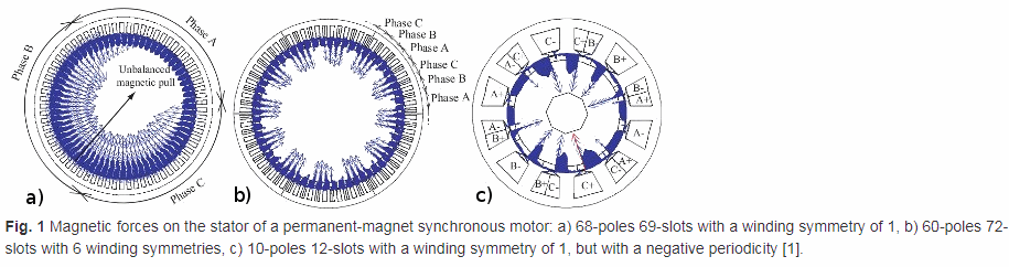
The winding symmetries indicate the number of rotational symmetries in the winding layout. This also indicates the machine symmetry for modelling. Inverse of the winding symmetries is the fraction of the motor that needs to be modelled for FEA load simulations(when the coils carry current, and with appropriate periodic boundary conditions).
Winding symmetries=GCD(PolePairs,Slots)
For example, winding symmetries for
- 6p9s is 3
- 8p12s is 4
- 8p18s is 2
The winding symmetries calculated is only indicative.
- When the magnetic periodicity is negative ( i.e. we can represent inverse direction of the magnetic field to represent the full motor) such as for integer slot windings and for some double layer windings with an even number of stator slots, the number of symmetries is double of that is calculated. i.e. we only need to model half of that is expected to be modelled and then apply negative periodic boundary.
- For some single layer concentrated windings, the effective number of windings may only be half of what is calculated.
There exist no symmetries for a winding symmetry of 1, but there may be some unbalanced magnetic radial forces causing vibration and noise.
Refer to this link
Slot pitch
This is the electrical angle between two slots.
** Slot pitch = Pole_Pairs * 360/SLOTS **
Phase group
This is the adjacent slots belonging to one phase under one pole pair. This number is same as SPP.
Phase spread
The electrical angle subtended by one phase group is called phase spread. This is SPP * SLOT_PITCH. For a 3 phase system, this becomes 60 degrees electrical.
Distributed winding
All the winding turns are arranged in several full pitch or fractional pitch coils. These coils are housed in the slots spread around the airgap periphery to form phase winding.
Wave winding
Lap winding
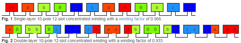
Concentrated winding
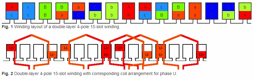
A winding is called concentrated winding if the number slots/pole/phase is fractional and lower than 1. For example, a 14p15s machine has 15/3/14=5/14 < 1. This results in a concentrated winding scheme.
This is usually a single throw winding, with a coil span of 1, and are non-overlapping.
This is a traditional BLDC winding, with short end-windings. Both single and double layer windings are possible. For double layer winding, the slot is divided (usually) vertically. Single layer winding is possible only when the slot count is a multiple of 6, because we need a repeatingn A-B-C- (6 characters , as opposed to ABC with 3 characters repeating for double layer winding) type and we need a balanced winding to make the instances of A, B, and C equal in the winding pattern.
But traditionally, some references exist to concentrated winding as having slots/pole/phase=1.
Concentric winding
All the winding turns are wound together in series to form one multi-turn coil. All the turns have the same magnetic axis. In this winding pattern, coils of the same group are laid in the slots such that the all the coils are concentric and their magnetic axes align.
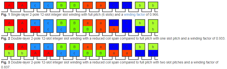
Integer slot winding
These windings have integer spp (slots/pole/phases). For example, 2 pole, 12 slot machine has spp=2. The integer slot winding has single layer winding for full pitch windings, and double layer winding when coil span is reduced compared to full pitch.
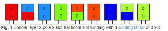
Fractional slot winding
A winding is called fractional slot winding when the number slots/pole/phase is fractional and more than 1. For example, a 2 pole 9 slot machine will have spp=9/2/3=3/2 > 1.
In this configuration, transposed winding is used to compensate skin effect for deeper wires in the slots. The Slots are divided horizontally(two halves as we go into the slot from the airgap).
Concentrated winding is also fractional slot winding, except that the spp < 1 for concentrated winding.
Fractional slot winding is possible with only double layered winding.
Winding factor
Windings with the same spp have same winding factor. The basic winding sequence is repeated for number of winding symmetries.
spp(10p12s)=12/10/3=2/5 spp(20p24s)=24/20/3=2/5
both have fundamental winding factor as 0.966, but with 1 and 2 winding symmetries.
WindingFActor=PitchFactorDistributionFActorSkewFactor
Pitch Factor
This is also called coil span factor or chording factor. This indicates if the windings are fully pitched or not, i.e. if the turns are reduced in slot pitches and do not cover full pole pitch or not.
Chording angle = PI(polepitch-coilpitch)/polepitch*. For a full pitch, the chording angle is 0.
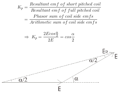
In a full pitched coil, the emf of two of the coil sides is exactly at 180 degrees offset. Since these terminals are in series, the voltages add up. For a short pitched coil, the emfs need to be vectorially added. Pitch factor is the measure of resultant emf of short pitched coil compared to the emf of full pitched coil. When the coil span is lower than pole pitch, the phasor sum of conductor voltages is less than the arithmetic sum, because of vector addition. The reduction fraction is the pitch factor.
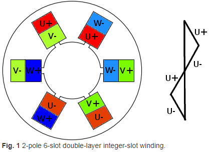
For example, the below image shows the 2p6s machine with double layer winding with the coil span being 2 slots (120 degree electrical) instead of 3 slots (180 degrees electrical).
fundamental pitch factor = sin((PI/2)coilSpan /PolePitch) nth order pitch factor = sin(n(PI/2)(coilSpan/PolePitch)
Pitch factor is for the fundamental component of the emf.
The flux wave may consist of space field harmonics also, which give rise to corresponding time harmonics in the generated voltage waveform. A 3rd harmonic component of the flux wave may be imagined to be produced by 3 poles as compared to the one pole for the fundamental component. Or alternatively, the 3rd harmonic component may be imagined as the voltage induced as a result of airgap flux density which is three times the frequency of number of poles, which was caused due to the time and space harmonics due to geometry.
All the even harmonics cancel out because the voltages oppose each other from the two coil ends and have net zero voltage. Only odd harmonics have effect.
For the example above, the pitch factor in the increasing order of odd numbers is 1: sin(PI/3) = 0.866 3: sin(PI)=0 5: sin(5PI/3)= -0.866 7: sin(7(PI/3) = 0.866 9: sin(3PI)=0
3rd harmonics and multiples of it are eliminated due to short pitching to 120 degrees (chording angle of 60 degrees). Generally, when the coil is short or long pitched to PI/n, no harmonics of the order n are present in the spectrum of winding factor.
Distribution factor
This is also called breath coefficient. This indicates the distribution of winding coils of each phase in the slots. If the coil ends of any one phase under one pole are bunched in one slot, the winding obtained is called concentrated winding and the total emf induced is equal to the arithmetic sum of the emfs induced in all the coils of one phase under one pole. But armature winding is not concentrated in most cases, and is distributed among many slots to form polar groups under each pole. In distributed winding, coil sides per phase are displaced from each other by an angle equal to the angular displacement of adjacent slots.

In the image above, each vector represents emf induced by a coil, and each coil is distributed by a slot angle(beta = 360/slots = 180/n). Let n =slots/pole, m=slots/pole/phases. Ec = induced emg per coil side.
emf in each coil side Ec = AC = 2 * OA * sin (beta/2) total emf = AB = 2 * OA * sin(m* beta/2)
distribution factor = sin(m*beta/2) / m / sin(beta/2), where m * beta is known as phase spread in electrical degree.
Distribution factor is given for the fundamental component of emg.
If the airgap flux density has harmonic components, the rth harmonic component = sin(r * m beta/2) /m/sin(r*beta/2)*
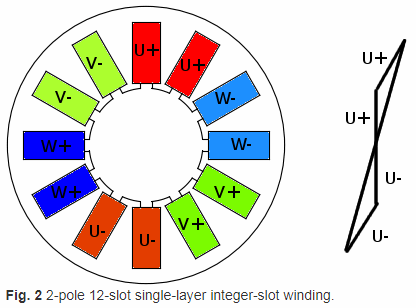
The following shows the 2p12s machine with single layer winding with spp=2.
When the conductors of one phase are distributed in a number of neighboring slots, the vector sum of conductor voltages becomes less than the arithmetic sum. This reduction is called distribution factor.
Distribution factor for nth order harmonics = sin(nPI/6)/poles/sin(nPI/6/poles) Distribution factor for fundamental is 0.5/poles/sin(PI/6/poles)=0.5/2/sin(PI/12)=0.966
The distribution factor takes care of individual coil separation, while the pitch factor takes care of separation of two coil ends.
Skew factor
The skew factor refers to how much the stator winding is angularly twisted (usually done to reduce cogging).
Skew factor for the nth harmonic can be calculated as sin(npolesskewangle_mr/4)/n/poles/(skewangle_mr/4)
For a 4p15s machine, the fundamental skew factor for a skew of 1 slot pitch ( 2*PI/15) is 0.971 ( 3% reduction of the value), but the 15th harmonic is 0 ( this is the cogging frequency).
In general, 1 slot pitch skew eliminates cogging with slightly reduced fundamental winding factor.
Harmonics elimination methods
Flux distribution in the airgap is usually composed of multiple frequencies, and is usualy non-sinusoidal. The induced emf on the windings may also be nonsinusoidal and contains harmonics.
- Star connections suppress 3rd harmonics from appearing across the lines
- Small airgap at the pole center and large airgap towards the pole ends
- Skewing
- Coil distribution
- Winding chording (short pitching)
- Fractional slot winding