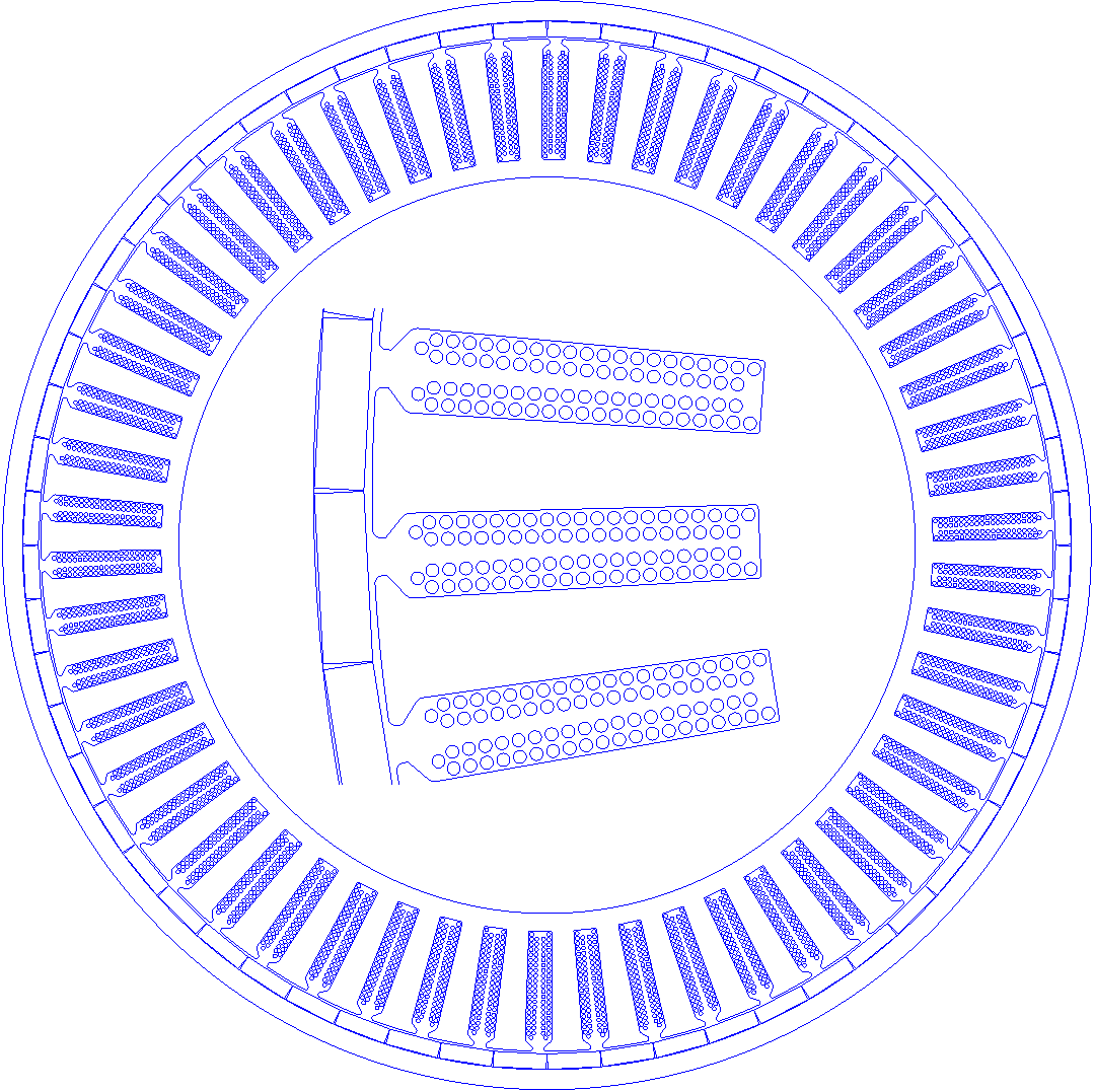
The rlib can create very fine details in the geometry including individual wire placement in the motor slots.
Positioning controls
The wire placement in the individual slots in the models is controlled by the following parameters.
Motor.Winding.Turns=6 // sets the number of turns for each occurrence of the phase letter in the winding pattern
Motor.Winding.NStrands=1 // sets the number of parallel strands for each winding turn
Motor.Winding.insulThickness=0.05 // sets the insulation thickness for the border line around the copper conductor
Motor.Winding.wiregap=0.1 // sets the wire spacing around the conductor from the insulation layer
Motor.Winding.SlotLinerThickness=0.1 // sets the slot liner thickness around the slot, this includes the slot hald seperator
Motor.Winding.throw=1 // when more than 1, refers to multi throw winding. Then the slot is split as horizontal.
Motor.Winding.Pattern // The winding pattern. for example AaABbBbBCcCcCAa
Motor.Winding.Slotsplit='vertical'// or horizontal

//either the following two lines
Motor.Winding.drawWiresEMag=1 // this flag decides whether to draw individual wires in the Electromagnetic solution mode. These are drawn by default in the thermal solution mode.
Motor.Winding.animate=1 // decides whether to animate the wire positioning or just place the wires in the geometry.
// or the following one line
Motor.buildModelIn='slot' // sets the above two lines internally, plots the slot view only in Scilab plot


// for circular wires
Motor.Winding.wireDia=1.016


//for rectangular wires
Motor.Winding.wire.rectangular=1// setting this flag will force the wires to be rectangular.
Motor.Winding.wire.len=1
Motor.Winding.wire.thick=2
Slot Split - horizontal vs vertical
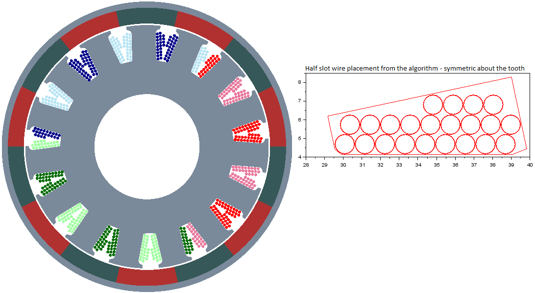
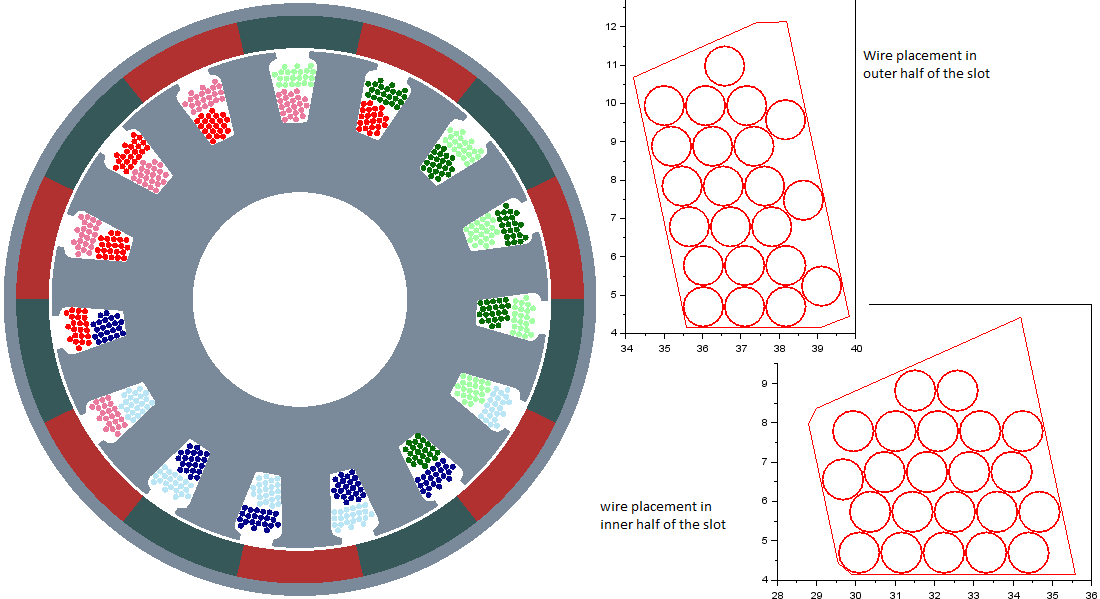
Wire placement algorithm
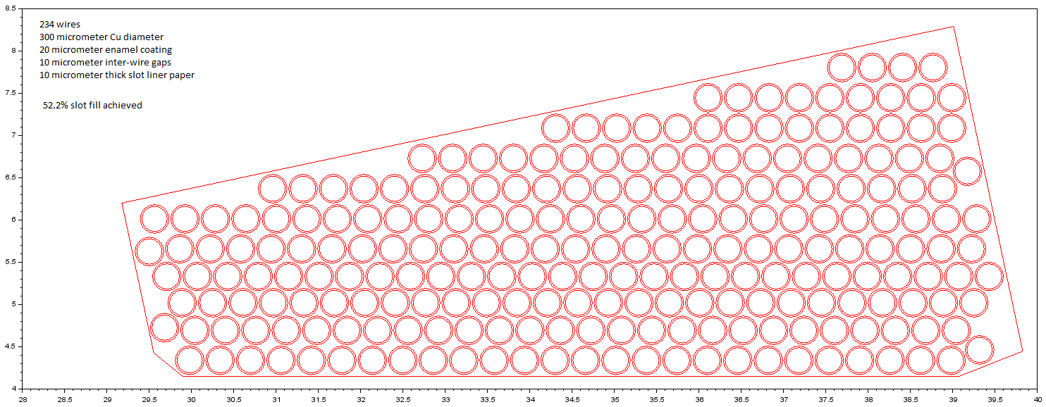
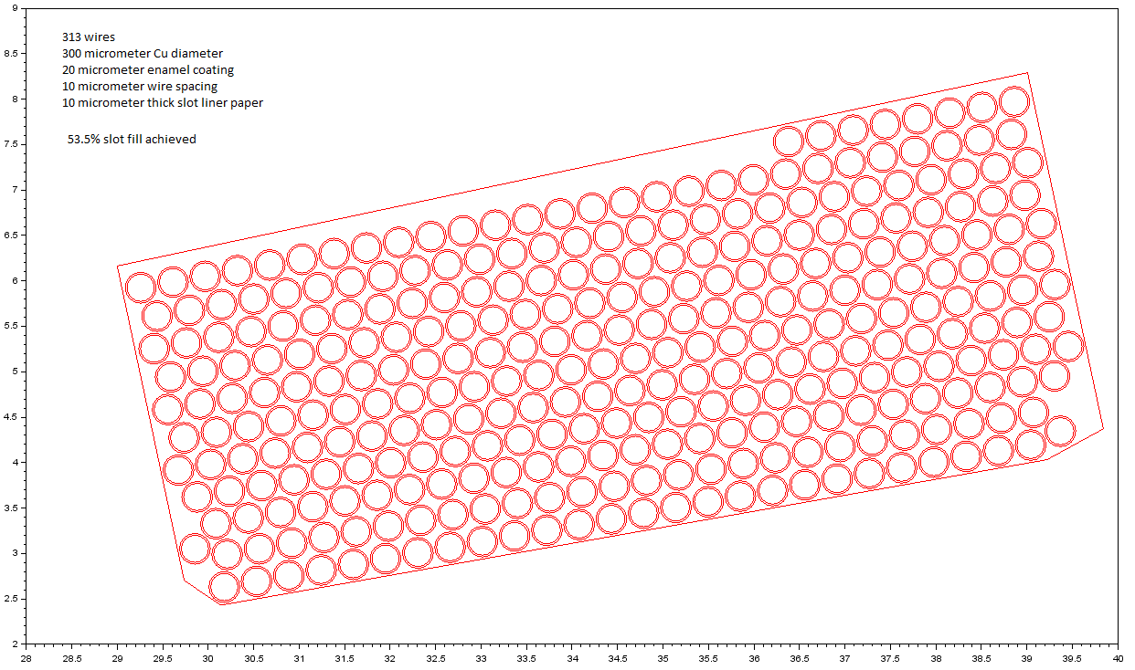
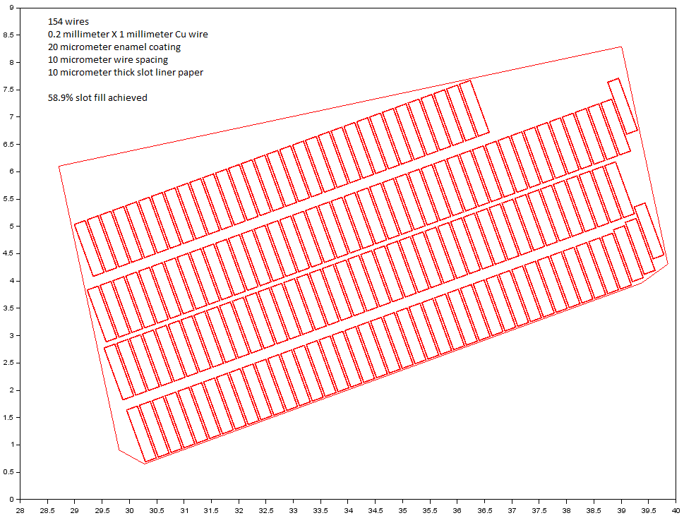
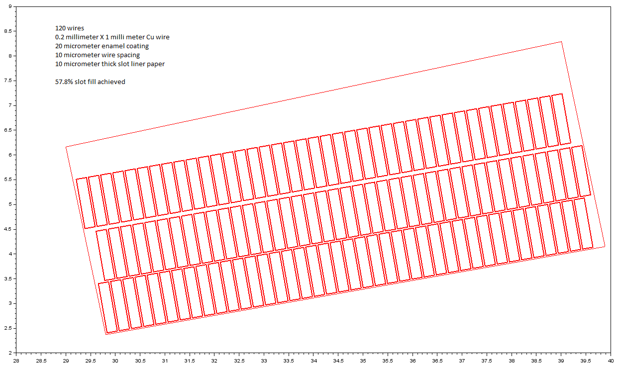
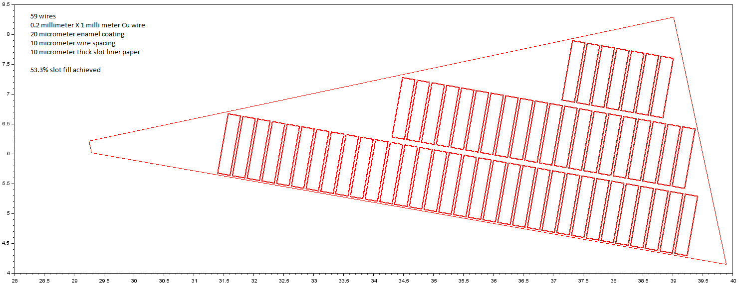
Below images show how the wire fill looks like for the given slot configuration with different angles of the bottom edge.
To present the working methodology of the algorithm developed by me, the geometric details are deliberately reduced to physically non-achievable levels. A realistic winding slot fill is about 40% through hand winding methods.
Wires with circular cross section
For one slot geometry
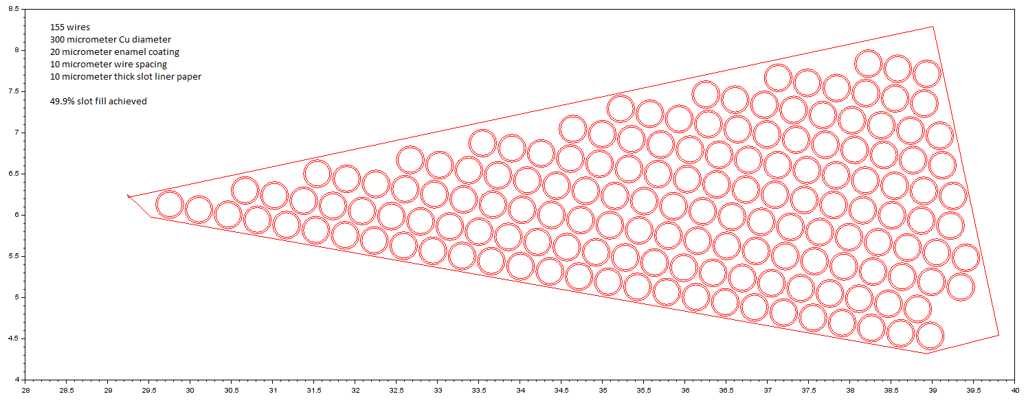
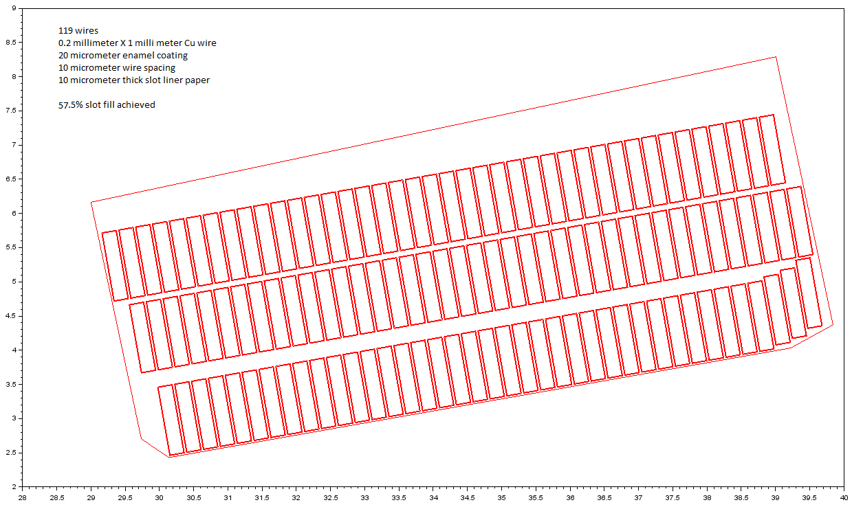
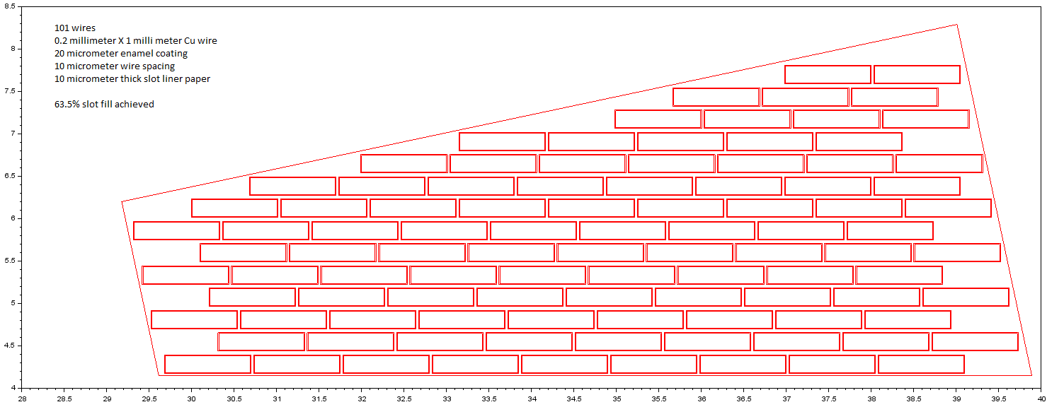
A different slot geometry
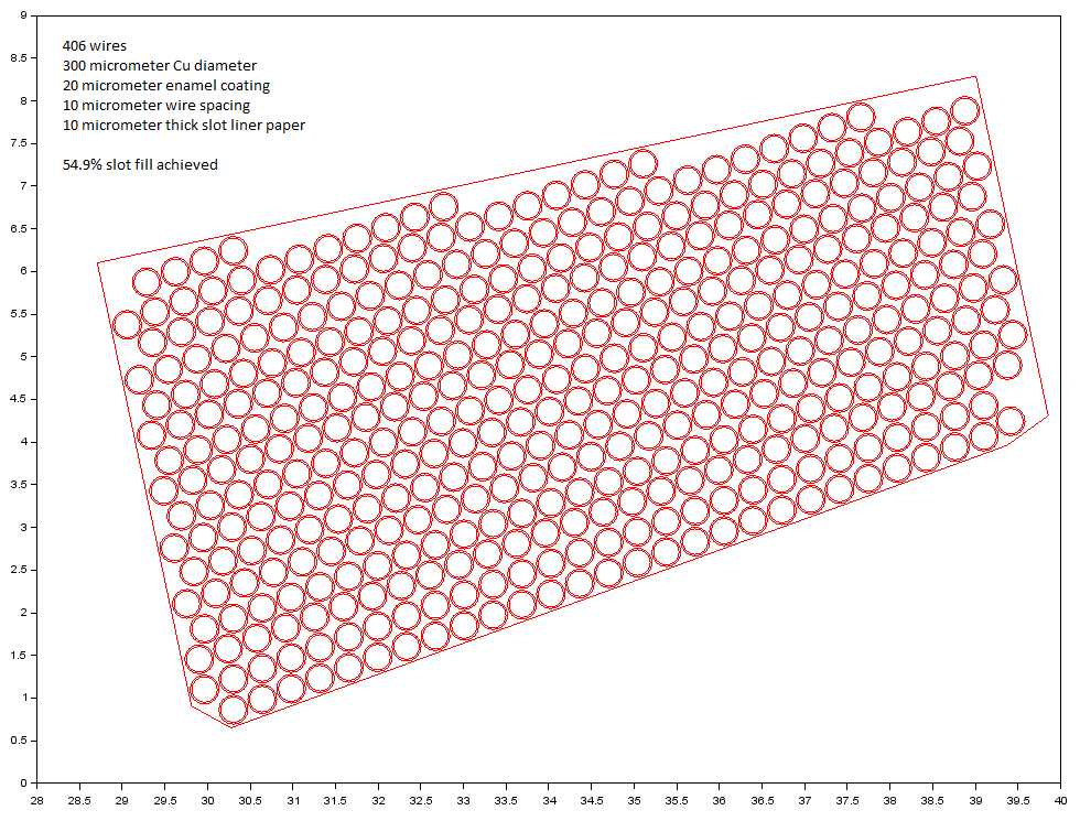
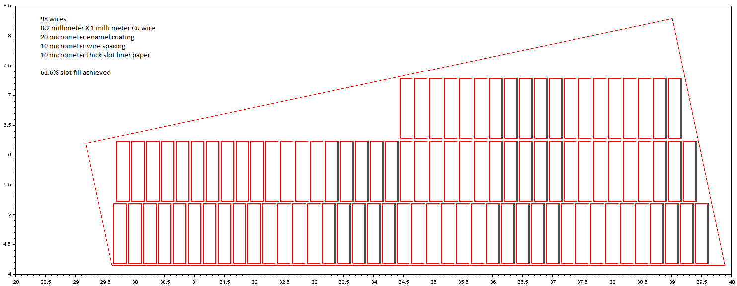
A different slot geometry
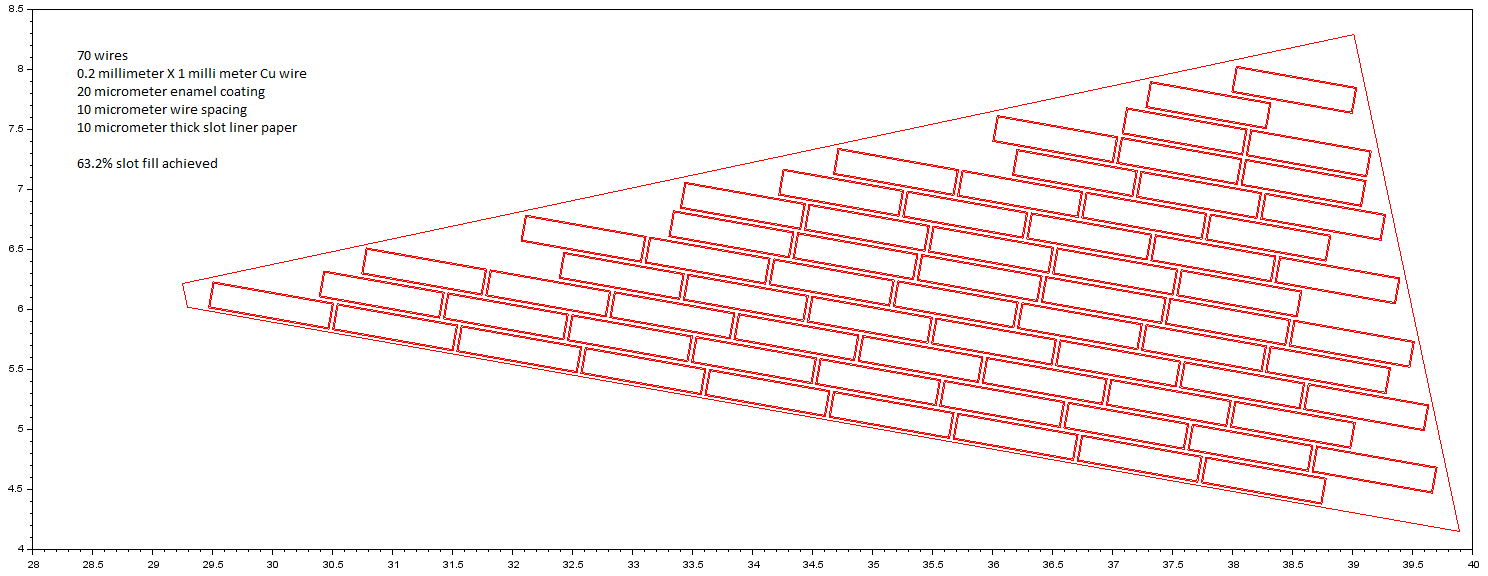
A different slot geometry
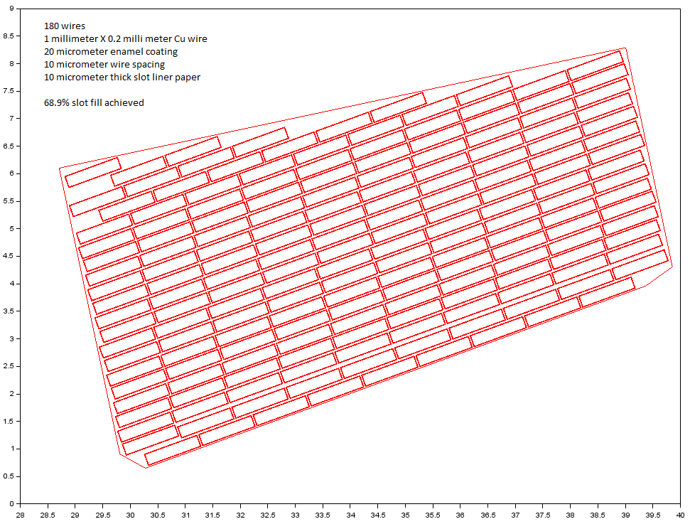
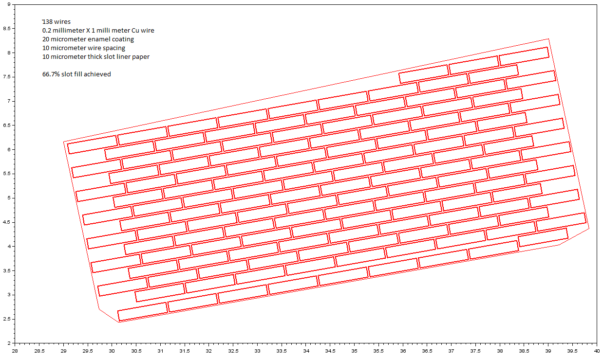
Wires with rectangular cross section
For one slot geometry
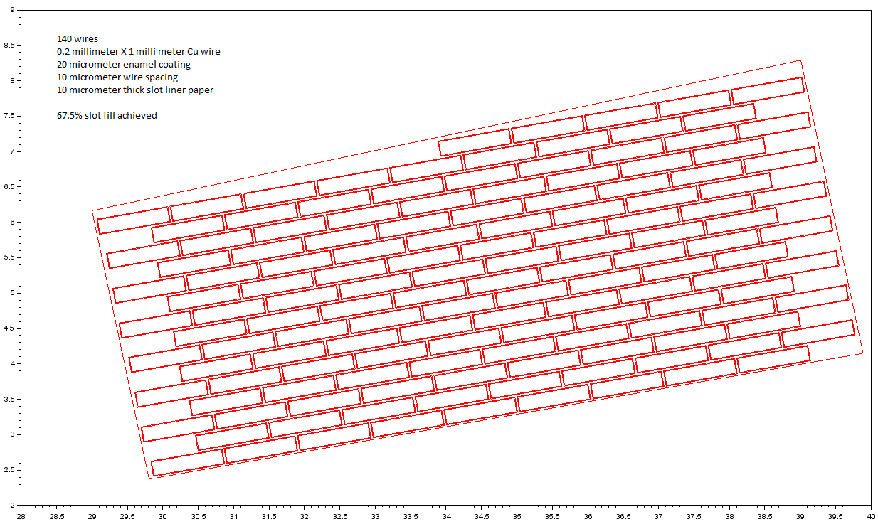
For the same slot geometry as above, but the wire rotated by 90 degrees
A different slot geometry
Same slot geometry a above, when the fillet radii are removed
Same slot geometry as above, but the wire rotated and the fillet radii are included
Same slot geometry as above, with the wire rotated and the fillet radii removed
Another geometry with no fillet radii
Same geometry as above with the wire rotated
Another geometry with no fillet radii
Same geometry as above, with the wire rotated
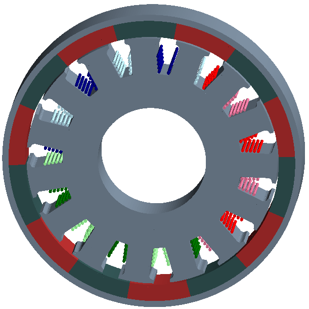
Some 3D examples
The rlib can create 3d models in Gmsh so far that can be meshed and imported to Elmer too. Below are some example images to demonstrate its 3D model building capabilities.
Circular wires in single throw winding configuration
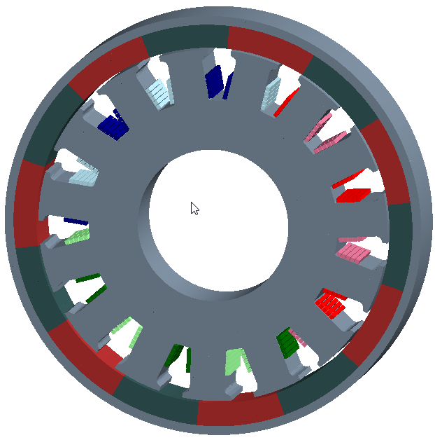
Rectangular wires in single throw winding configuration
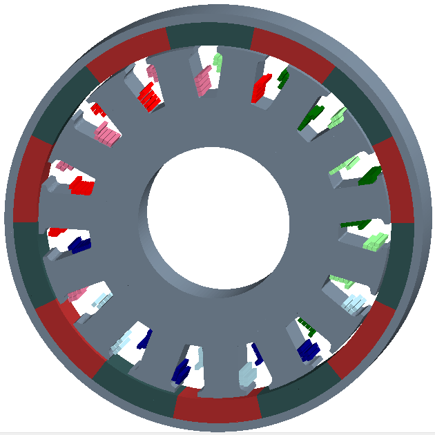
Rectangular wires in multi throw winding configuration
Software operational time comparison
When the individual wires are created in the geometry, the number of nodes increase dramatically. Different software are written to handle these nodes differently.
The following exercise of creating the motor geometry and mesh generation has been done with one of the motor designs with three software - FEMM, FLUX and GMSH.
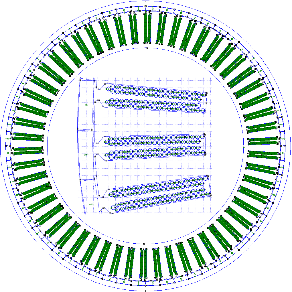
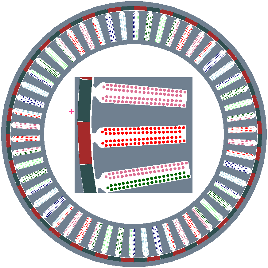
A sample motor design from a Chinese manufacturer is taken for plotting these below geometries in different software. Individual wire placement is shown in the inside of each image.
The results and comparisons are as below
| TOOL | Time to Create Geometry | Time to Re-open Geometry | Time to Mesh domain | Nodes in the mesh |
|---|---|---|---|---|
| FEMM | 6.5 minutes | 3 seconds | 1.5 minutes | 2.6 million |
| FLUX | 130.0 minutes | 21 seconds | 73.0 minutes | 4.8 million |
| GMSH | 38.0 minutes | 17 seconds | 2.5 minutes | 3.3 million |
FEMM creates the following geometry
FLUX creates the following geometry
GMSH creates the following geometry